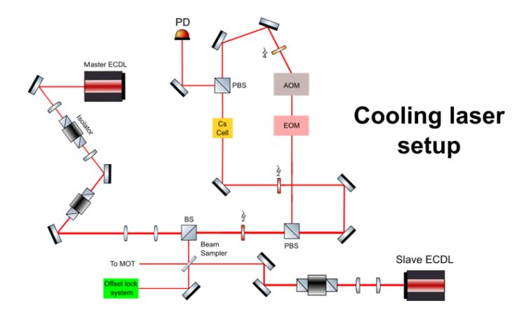
1.852 nm system

In 852 nm system, we use two laser sources. One is master laser and the other is slave laser. For master laser, we let the laser light pass through the AOM to derive the saturated absorption spectroscopy, and then by EOM to derive the frequency modulated signal. With this signal, we can use frequency locking system to lock the master laser frequency. After that, we use offset locking system to lock the slave laser frequency with a frequency offset compared with the mater laser. Then we introduce the frequency-locked slave laser into the MOT for cooling down the Cs atom. Besides, by tuning the frequency offset, we can also scan the slave laser frequency.

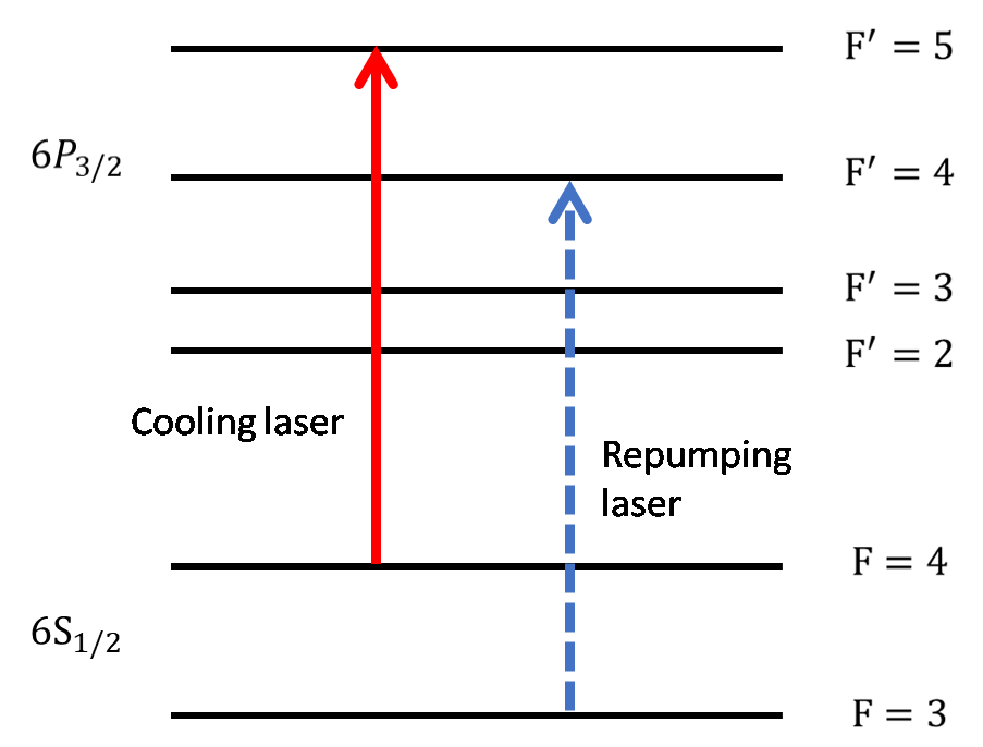
2. Repumping laser system

For the cooling laser in 852 nm system, the laser frequency is resonant with D2 line of Cs atom, that is, F=4 of ground state to F’=5 of excited state. However, it is possible to transit from F=4 to F’=4 and then relax to F=3 of ground state, which causes the depopulation of F=4 level. In order to prevent the situation from happening, it is necessary to use repumping laser resonant with F=3 to F’=4 to remove the population of atoms in ground state F=3 so that they can take part in the cooling cycle and remain good efficiency of cooling.

3. Magnetic Optical Trap (MOT)

This MOT we using in our laser cooling experiment have two functions, to cool down the atom and to capture the cooled atom. These two function are activated at the same time. The frequency locked slave laser the 852 nm system is introduced into the MOT system and being separated into six beams. These beams are used to decrease the momentum of the Cs atom, and then cool down the atom’s temperature. And around the MOT, we build two anti-Helmholtz coils to generate Zeeman effect on the atoms. This Zeeman effect along with the six laser beams will generate a restoring force to trap the Cs atom at the intersection point of six laser beams.
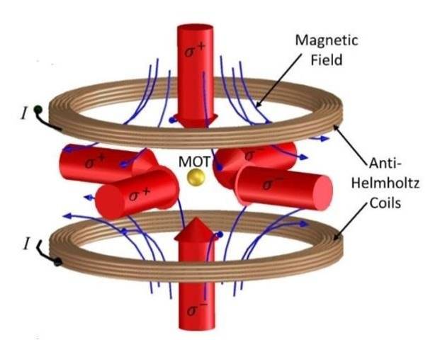
Source: https://www.researchgate.net/figure/conceptual-scheme-of-a-magneto-optical-trap-MOT-and-typical-expansion-of-a-cloud-of_fig4_348383229

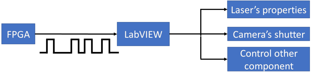
4. FPGA and LabVIEW application

To fulfill the automatic control of the MOT, we plan to combine FPGA and LabVIEW and apply them into the experiment. The basic idea is to use FPGA to generate many signal trigger that has special time interval between each other. After receiving this certain trigger signal series, the program in LabVIEW will determine how to change laser’s properties, or to set when to activate camera’s shutter or to control other component.

5. Future plan

(1) To observe the EIT from two photo translations.
(2) To see the Ramsey fringe for a new way to make an atomic clock with comb laser which can precisely control the pulse interval time and the phase.